Many times Ive had to go through old documentation to figure out how to wind a transformer. This means that an SE transformer must be constructed differently from a push-pull type.
Ultra Linear Output Transformers
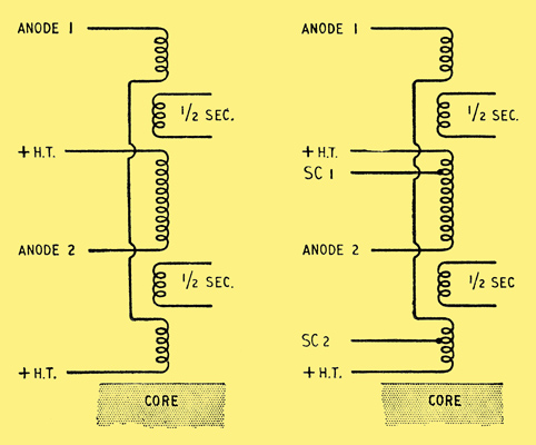
An output transformer designed for push-pull operation has a centre tap.

. A push-pull converter opens up lots of conversion possibilities such as Buck Boost Buck-Boost isolated or even non-isolated topologies also it is one of the oldest switching topologies used in power electronics that require minimum components to produce medium power outputs Typically - 150W to 500W with multiple output voltage. Flyback transformers actually coupled induc-tors are covered in a later Section. These power supplies are known as switched-mode-power-supplies SMPS.
Determine the V-T value based upon the maximum allowable duty cycle and the frequency. Building the Mullard 5-10 Amplifier. Forward converter bridge half-bridge and full-wave center-tap.
For square wave K f 4 K u Window utilization factor J Current density B max Operating flux density F Switching frequency P o Output power. Buy Today Get Your Order Fast. Power level up to 300 watts.
Wide Selection of Power Products In Stock at Allied. How to Design an Isolated High Frequency Push-Pull DCDC Converter. Silver wire windings available at current market prices.
As an example you might want to design an output transformer for a single pair of 6L6 output tubes. The W a A c power output relationship is obtained by. Lowest full power frequency.
It is a simple calculator - it just. Testing the Mullard. Single secondary impedance models available these usually have extended high frequency response.
Compensated in the transformer core while in push-pull transformers the quiescent currents of the two push-pull power tubes cancel each other out in the core of the OPT. In this way current flows in opposite directions through the output transformer. 4 Core types All cores used for tube output transformers are laminated that is they consist.
PUSH-PULL OUTPUT TRANSFORMERS FEATURES Our power output transformers use the best grade M6 low-loss grain oriented silicon iron laminations. This work also try to implement MATLAB tools simulation of push pull converter with a center tap high frequency transformer. A simple push-pull DCDC converter with a fixed 50 duty cycle is often used as a low noise transformer driver in communication systems medical instruments and distributed power supplies.
I have designed the MPPT algorithm magnetic components etc and. Wiring up the primary. K f Form factor.
The amplified audio from the 2 output valves push pull is in opposite phase 180deg. TYPE click for spec. Volt-Time Product V-µSec Value.
2 Push-Pull Transistors Semelab plc produces a wide range of push-pull MOSFETs and this application note is intended as a guide to some circuit design principles which are particularlyappropriate when using these devices. For the purpose of design demonstration assume that a plate modulation transformer is required for the following conditions of operation. High permeability materials make it possible to design high bandwidth transformers but such a transformer is also very sensitive to DC magnetisation.
Section 4 Power Transformer Design Power Transformer Design This Section covers the design of power trans-formers used in buck-derived topologies. Fixed bias Guitar 3k5. It is often used to change a power supplys DC voltage.
PUSH-PULL CIRCUITS and WIDEBAND TRANSFORMERS. I decided to put the calculations in a web-based calculator. Modulator output is push-pull pentodes requiring load impedance of 10000 ohms and that each tube draws 60 ma.
A pushpull transformer is a DC-to-DC switching transformer. They are lower in cost. Two examples of Semelab push-pull MOSFETs are shown in figure 1.
From the tube data books you determine that a pair of 6L6s will put 40-50W in Class AB push pull into a 4400 ohm plate to plate impedance. The HT is applied to the centre tap and either end of the primary winding is connected to the anode of a power valve. Older linear power supplies often used low frequency heavy silicon steel type transformers to step down incoming line voltage to something smaller that was then rectified.
You know you would like to match this impedance to loads of 8 and 4 ohms and this will be used for. Primary Windings ships copper mains transformers. The Mullard 3-3 an excellent choice for a first amp.
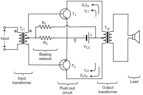
300VAC 300VAC 600V AC is across the primary winding. The objectives are realized and outlined in various Sections as follows. A push pull amplifier is an amplifier which has an output stage that can drive a current in either direction through the load.
The output of a typical push pull amplifier consists of two identical BJTs or MOSFETs one sourcing current through the load while the other one sinking the current through the load. Ad Buy Current Transformers Voltage Power Transducers. Choice of core material also affects the performance of the transformer.
The very versatile PWHT01 and PWHT02 transformer. Audio output power to be 75 watts. We wind our push-pull output transformers on two chamber bobbins which ensures full capacity and resistance balance.
Depending on the tranny design there may be 2000 turns of wire in the Primary and 90 turns for the Secondary winding. The input is 30V and the output is 400V with the power of 400W. SMPS Push-Pull Transformer Calculator Another Transformer Calculator.
I have designed a Push-pull converter as shown at the attachment. This simple scheme provides no voltage regulationrequiring a low dropout. Ad Search Thousands of Catalogs for Output Transformer Design.
PUSH-PULL OUTPUT TRANSFORMERS By valve type and configuration CLICK HERE FOR DIMENSIONS. Illustration of Class B and Class AB Push-Pull Source Follower Output current and voltage characteristics of the push-pull source follower RL 1kΩ-2V-1V 0V 1V 2V-2 -1 0 1 2 VinV 1mA 0mA-1mA vout vG 1 G2 iD1 iD2 Class B push-pull source follower-2V-1V 0V 1V 2V-2 -1 0 1 2 VinV 1mA 0mA-1mA vout vG1 iD iD2 Class AB push-pull source. In general one can say that a SE-transformer includes a gap in the core to deal with the quiescent.
All push-pull designs will exceed 20 to 20 kHz -1db bandwidth. Dc per side mA. In this paper is to design a push pull converter which can gain output 300V DC from 12V DC input.
By Dawson Huang Download PDF. This ensures minimal distortion and low insertion loss.

10k Push Pull Output Transformer Power 8w Ei57 Double E Core Primary Wire Diameter 0 13mm Can Pass 35ma Current Transformers Aliexpress
Wtf Push Pull Output Stage Diyaudio

How To Design An Isolated High Frequency Push Pull Dc Dc Converter Analog Devices
![]()
Pulser Topology With Transformer Push Pull Output Download Scientific Diagram
How To Design An Isolated High Frequency Push Pull Dc Dc Converter Analog Devices

Push Pull Switching Transformer Design Cet Technology
Electronic Transformers Push Pull Amplifier Transformers
Push Pull
0 comments
Post a Comment